Isolate Relevant Parts of a Point Cloud
Learn how to use the cropping tool to isolate relevant parts of your point clouds by drawing fences, circles or windows and combining them to create complex crop regions
Overview
Large point clouds often contain surrounding context, temporary objects, neighboring buildings, or scan noise that is useful in some situations but distracting in others. Clipping sections provide a fast way to reduce this visual complexity. They are especially helpful when checking a facade, isolating a floor area, reviewing an installation zone, comparing scan data against model geometry, or preparing a focused working view for a repeated workflow.
Example: A user is reviewing scan data around a building entrance. The full point cloud also contains the street, parked vehicles, neighboring facade areas, and scan points behind the entrance zone. Before checking the entrance geometry against the model, the user creates a clipping section around the entrance. The view becomes easier to read because only the relevant scan points remain visible, while the surrounding context can still be restored later by returning to All Points in the clipping manager.
A clipping section is created by drawing shapes on the active view. You choose a clipping tool, draw a region on screen, and Qbitec projects that region through the visible point cloud. The resulting section is applied to the point cloud display. By default, points inside the drawn region remain visible and points outside it are hidden. If the operation is inverted, the drawn region becomes the part that is removed instead.

Clipping tools inside the Qbitec ribbon of Qbitec for Autodesk Revit
Clipping is not limited to a single operation. You can create several sections one after another to refine the result. Consecutive clipping operations narrow the visible set, which is useful when a region must be isolated from more than one view direction. Existing Revit view restrictions, such as a section box or view range, are respected and become part of the effective clipping definition. Saved clipping regions are stored in the Revit project so they can be reused later.
Creating Clipping Regions
Qbitec provides three drawing tools for creating clipping sections: Fence, Window, and Circle. The best choice depends on the shape of the area you want to keep or remove.
During creation, view navigation such as zoom, pan, and orbit is temporarily disabled until the clipping operation is completed. This keeps the drawn screen geometry consistent with the view direction used for the projection.
| Button | Function | Purpose |
|
|
Draw fence |
Creates a polygonal clipping section from three or more points |
|
|
Draw window | Creates a rectangular clipping section from two opposite corners. |
|
|
Draw circle | Creates a circular clipping section from two diameter points. |


The Fence tool is the most flexible option. It creates a polygon from the points you place in the view and is suited for irregular boundaries such as building outlines, excavation limits, plant rooms, stair cores, or scan areas that do not fit a simple rectangle. Click to place each vertex of the polygon. At least three points are required. If the last point is wrong, press BACKSPACE to remove it. Press ENTER to confirm the fence, or press ESC to cancel the operation.
The Window tool creates a rectangular section. It is the quickest option for orthogonal work areas, elevations, rooms, shafts, or scan strips. Click the first corner of the rectangle, then click the opposite corner. The rectangle is applied immediately after the second point. Press ESC before completion if you want to cancel the operation.
The Circle tool creates a circular section from two points that define the diameter. It is useful for columns, shafts, tanks, manholes, local MEP work, or any review area that is naturally radial. Click the first diameter point, then click the second diameter point.

All three tools support inverted creation. Hold SHIFT while placing the first point to invert the new section. In the normal mode, the inside of the drawn region is kept. In inverted mode, the inside of the drawn region is removed and the outside remains visible. This is useful when a small object, noisy scan area, or temporary obstruction must be cut away without redrawing the larger surrounding area.

Inversion can also be applied after a valid clipping state already exists by using the Invert command. This flips the current result, which is useful when you first isolate an area precisely and then want to hide exactly that area.
Example: To isolate an irregular main building footprint, the user first sets up a suitable top or 3D view and chooses Fence. They click around the visible outline of the building, remove a misplaced vertex with BACKSPACE, and confirm the polygon with ENTER. From another view direction, they add a Window section to remove scan points above the relevant floor range. Later, a circular area around a column can be kept with Circle, or removed by holding SHIFT on the first diameter point when the column scan should be excluded from the result.
Managing, Saving & Combining Regions
The Qbitec tab contains the following button to manage clipped regions and combine them:

This dialog is the central place for switching between saved regions, restoring the full point cloud, saving the current clipping result, combining regions, and deleting regions that are no longer needed.
Dialog elements
The dialog consists of the following parts:
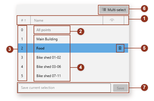
| Number | Name | Purpose |
| 1 | Header row | Toggle sort direction by clicking a header row |
| 2 | Show all points | Deactivate all clipped regions and show all points |
| 3 | Index | Stable index ordered by the time point of creation |
| 4 | Region names | Names of the regions. Double-click the name to edit |
| 5 | Delete region | Removes a region from the list and the project |
| 6 | Multi-select | Switch the dialog to a multi-select state to combine regions |
| 7 | Save | Saves the current regions to a new list entry |
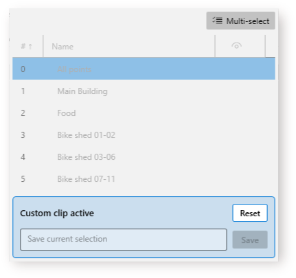
The first entry in the list is All Points. Selecting it restores the default state where no clipping is applied and the full point cloud is visible. "All Points" is a special entry: it cannot be renamed, deleted, or modified. It acts as the baseline that you return to before starting a new independent clipping setup.
Each saved clipping region has an index and a name. The index provides a stable reference, while the name should describe the practical purpose of the region, such as "Main Building", "North Facade", or "Bike Shed". You can edit a region name by double-clicking it.
Clear names are important when several team members work with the same Revit project or when a project accumulates many focused regions over time.
To save a region, first create the clipping result you want. This can be a single Window, Fence, or Circle section, or it can be a refined result built from several consecutive operations. Then open the manager and save the current view as a new region. The saved region is stored in the Revit project and remains available across sessions.
Combining regions
Regions can also be combined. When Multi-select is enabled, multiple saved regions can be active at the same time. In that mode, selected saved regions are combined with an OR relation: points are visible if they are inside any selected region. This is useful for showing several separate areas together, such as a main building and an outbuilding, without merging them into one manually drawn boundary.
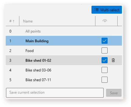
Delete removes a saved clipping region from the project. The delete button is available for regular saved regions, but not for All Points. Deleting a region does not delete point cloud data; it only removes the stored clipping definition. Before deleting shared project regions, make sure the region is no longer needed by other workflows or team members.
Example: A user isolates the main building with several Fence operations and saves the result as "Main Building". They then select All Points to restore the full cloud, isolate the bike shed as a separate area, and save that result as "Bike Shed". Later, when both areas must be shown together, the user enables Multi-select, selects both saved regions, and saves the combination as "Main Building with Bike Shed". If an older temporary region is no longer useful, they delete it from the manager; the point cloud data itself remains unchanged.