In this tutorial, you will learn how to
- Add a georeferenced Qbitec point cloud to a local Revit® project
- Align the point cloud to your model
- Set the survey coordinate system to the georeference of the point cloud
- Optionally add more georeferenced point clouds to the project
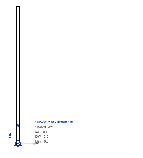
- Open a Revit project that is not yet georeferenced. The image shows a project consisting of two walls. The survey point (triangular blue symbol) is at the origin, has 0 coordinates and the axes run parallel to the project coordinate system.
- Click on the “Insert Point Cloud” button in the “Qbitec ribbon”

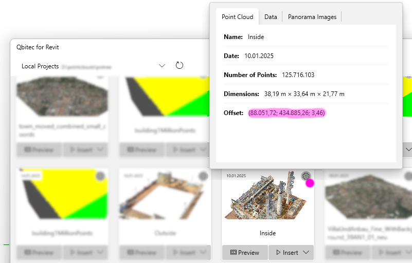
- Select a point cloud that is georeferenced. This can be recognized by the large x and y coordinates in the offset. You can display the offset by clicking on the cogwheel in the tile.
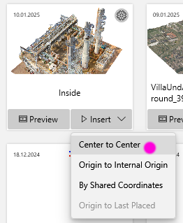
Click on “Insert” under the point cloud to be inserted and select the option “Center to Center”.

- The point cloud appears in the middle of your project. It is aligned to true north and probably does not yet match your Revit model. You may not be able to see your model because it is obscured, as in this example.
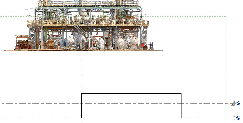
- Establish the height reference by switching to a side view (e.g. south). Unlock the point cloud by clicking on the pin. As a result, the pin is crossed out.
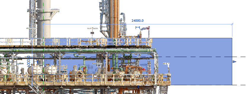
- Move the point cloud so that it matches your height system. In the “Modify” ribbon, use the button

The result for the example looks like this.
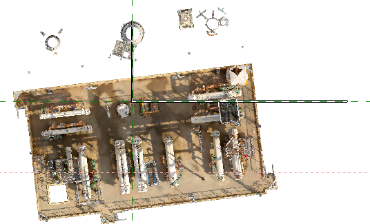
- Switch to the top view.
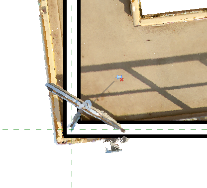
- Now move the point cloud so that one point of the cloud matches your model. In the example, our aim is for the intersection of the two walls to be at the bottom left-hand corner of the upper floor of the chemical plant. The handrail should fit snugly against the walls from the inside. In the “Modify” ribbon, use the button

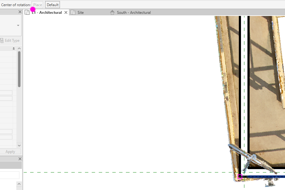
- Rotate the point cloud so that it fits your project completely. In the “Modify” ribbon, use the button

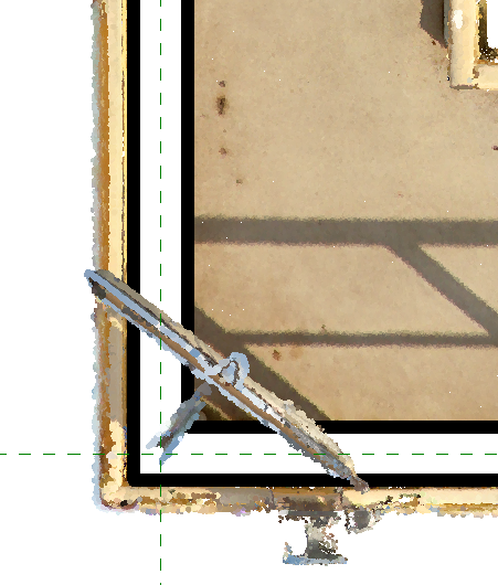
As the “Center of Rotation; Place”, select the point that already matches.
-
Then click on a corresponding axis in the point cloud and then on the model. This should be as long as possible to achieve a high level of accuracy.
As a result, the point cloud is aligned with your model.
Check the result on other model parts and repeat steps 4 to 6 (shift and rotation) until the match is accurate enough.
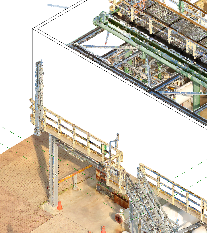
The point cloud and Revit model now also fit perfectly in an oblique view.
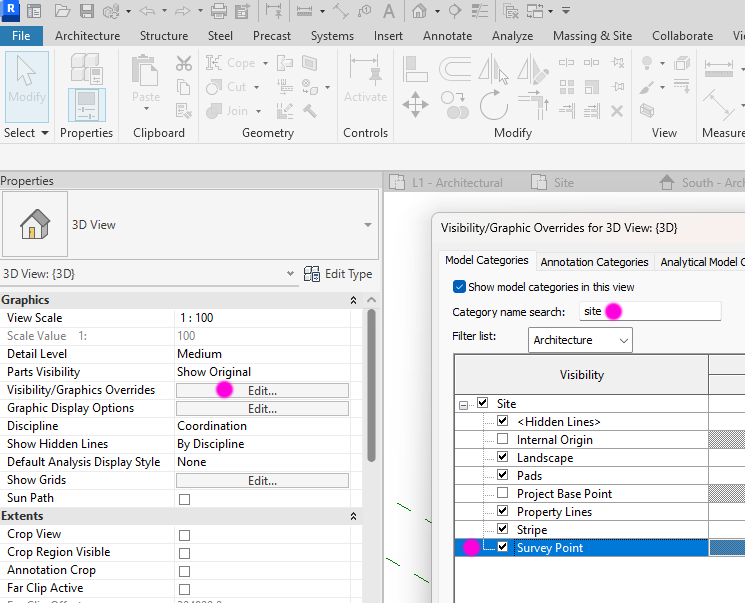
- Select a view with the survey point displayed or switch it on in any view.
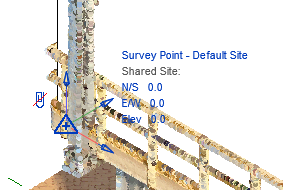
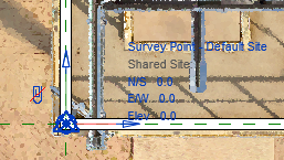
- Switch off the paper clip on the measurement symbol by clicking on it. The result is a red crossed-out paper clip. Here in oblique and top view.
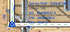
- Click on the “Set Survey System” button in the “Qbitec ribbon”

and then anywhere on the point cloud to indicate that the measurement system is to be taken from this point cloud. The software then reads the coordinate system from the point cloud and writes it to the Revit survey coordinate system (“shared coordinates”). The result is large numerical values at the survey point and the axes are rotated according to the geographic north.
The survey point is usually moved to a point whose geographic coordinate is known, e.g. to a boundary stone. The crossed-out paper clip indicates that this movement does not change the origin and orientation of the coordinate system. Only the symbol is moved. In the example, we leave the survey point at the origin of the project coordinate system.
You can now save the project and work on the Revit design as required.
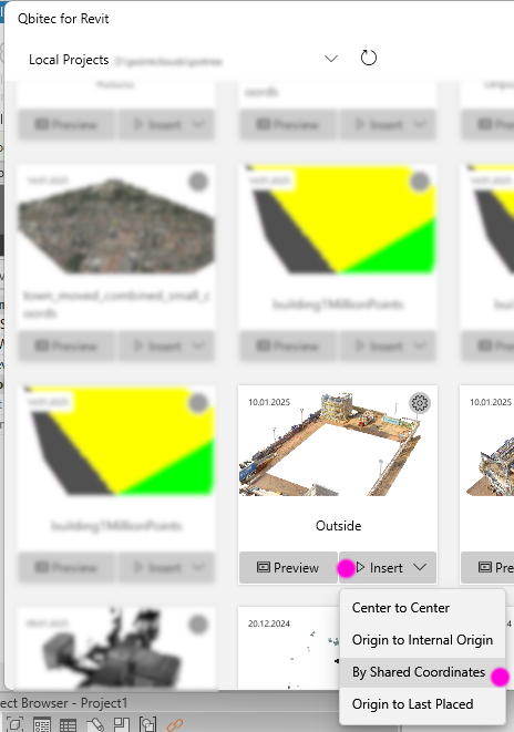
If you want to insert additional georeferenced point clouds, you can do so at any time. Click the “Insert Point Cloud” button in the “Qbitec ribbon”

Select the point cloud and click on “Insert”. Use the “By Shared Coordinates” method to insert the point cloud according to the survey coordinate system saved in the cloud.
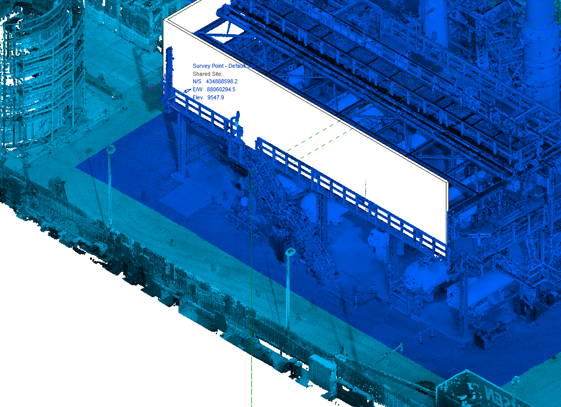
Both point clouds and the Revit model then match exactly. Use the “Cloud” colour mode in the “Qbitec Ribbon” to visualize the result: ![]()
Both point clouds are thus colored differently..
And that's it! If you have any questions, please contact us via support@qbitec.com.
Here is a video that demonstrates the process similar to this tutorial.
