Point Cloud Display Settings
Settings are stored per view
Adjusting the Point Size
The point size used for rendering the point cloud can be adjusted. Three predefined options are available: Automatic, Medium, and Fine.
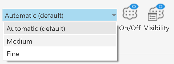
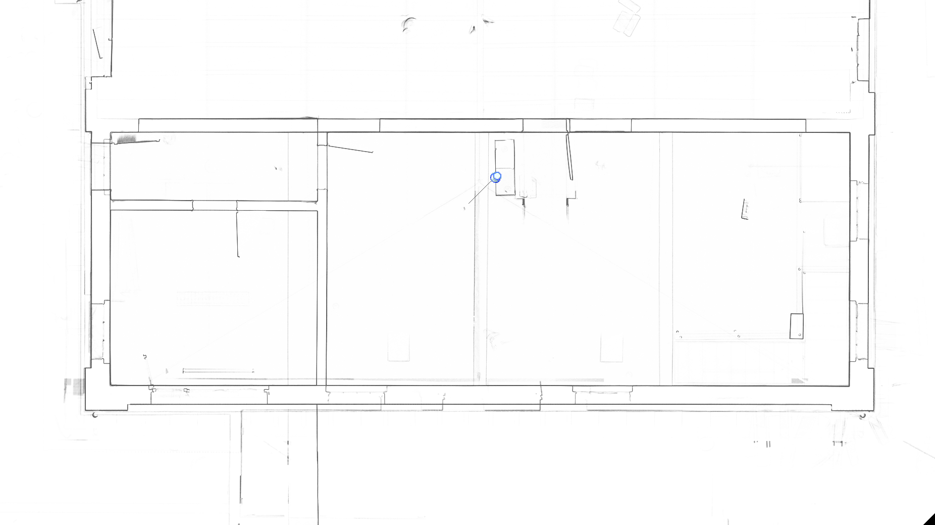
Fine
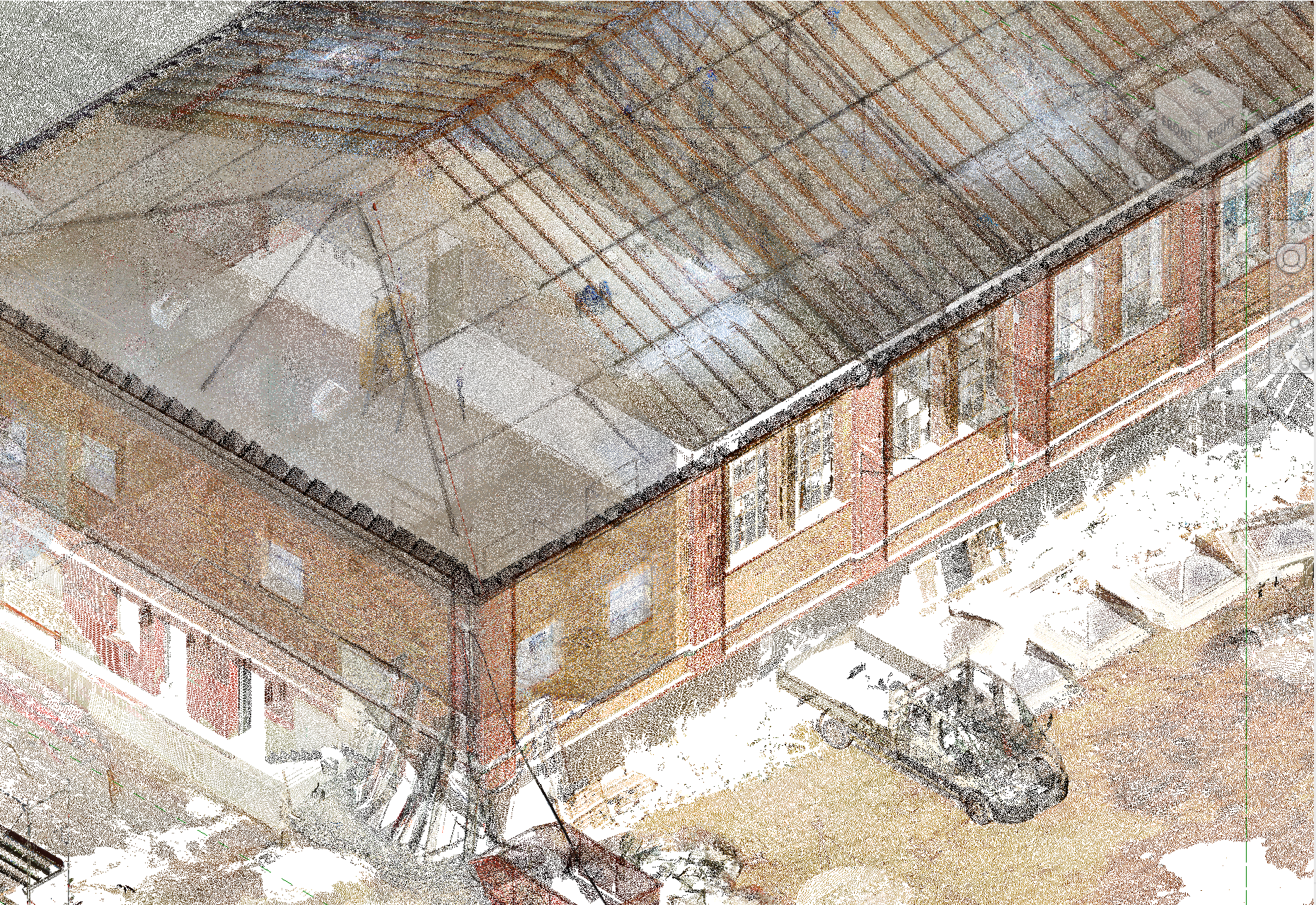
The Fine setting uses a small point size similar to the point cloud rendering used to display ReCap point clouds in Revit. This can often create the effect that the point cloud becomes visually sparse, allowing the viewer to see through it so that surfaces become difficult to recognize.
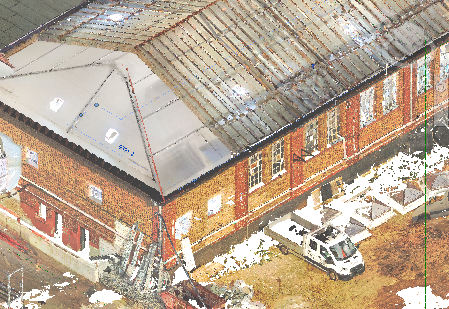
Automatic (default)
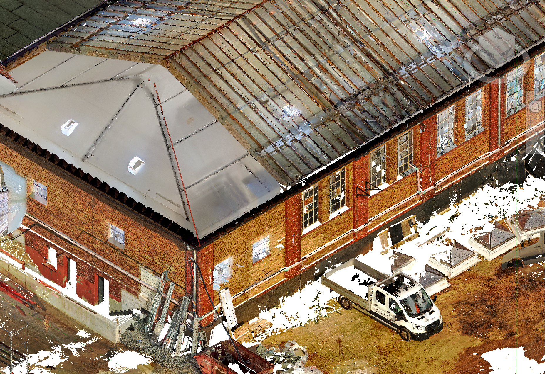
The Automatic setting attempts to choose a point size that keeps surfaces such as walls visually closed and easier to interpret, while Medium provides a compromise between the two extremes.
For additional control, the point size can also be manually adjusted.
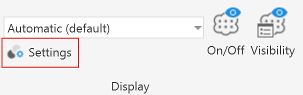
Therefore open the display settings by clicking on the Settings-button
And adjust the Point size using the point size slider.
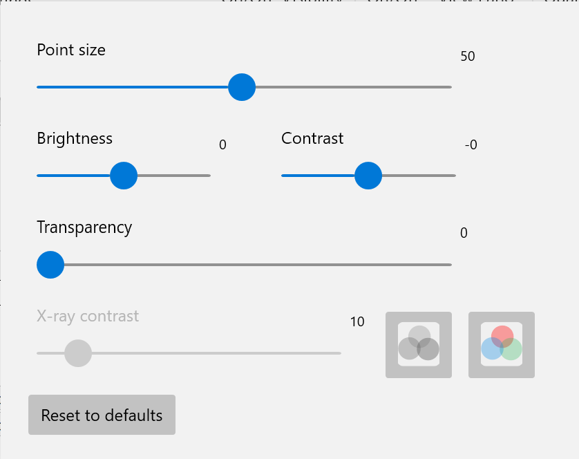
In the Setting Window you can also find a few other settings to control the visual appearance of point clouds.
Brightness and Contrast Slider
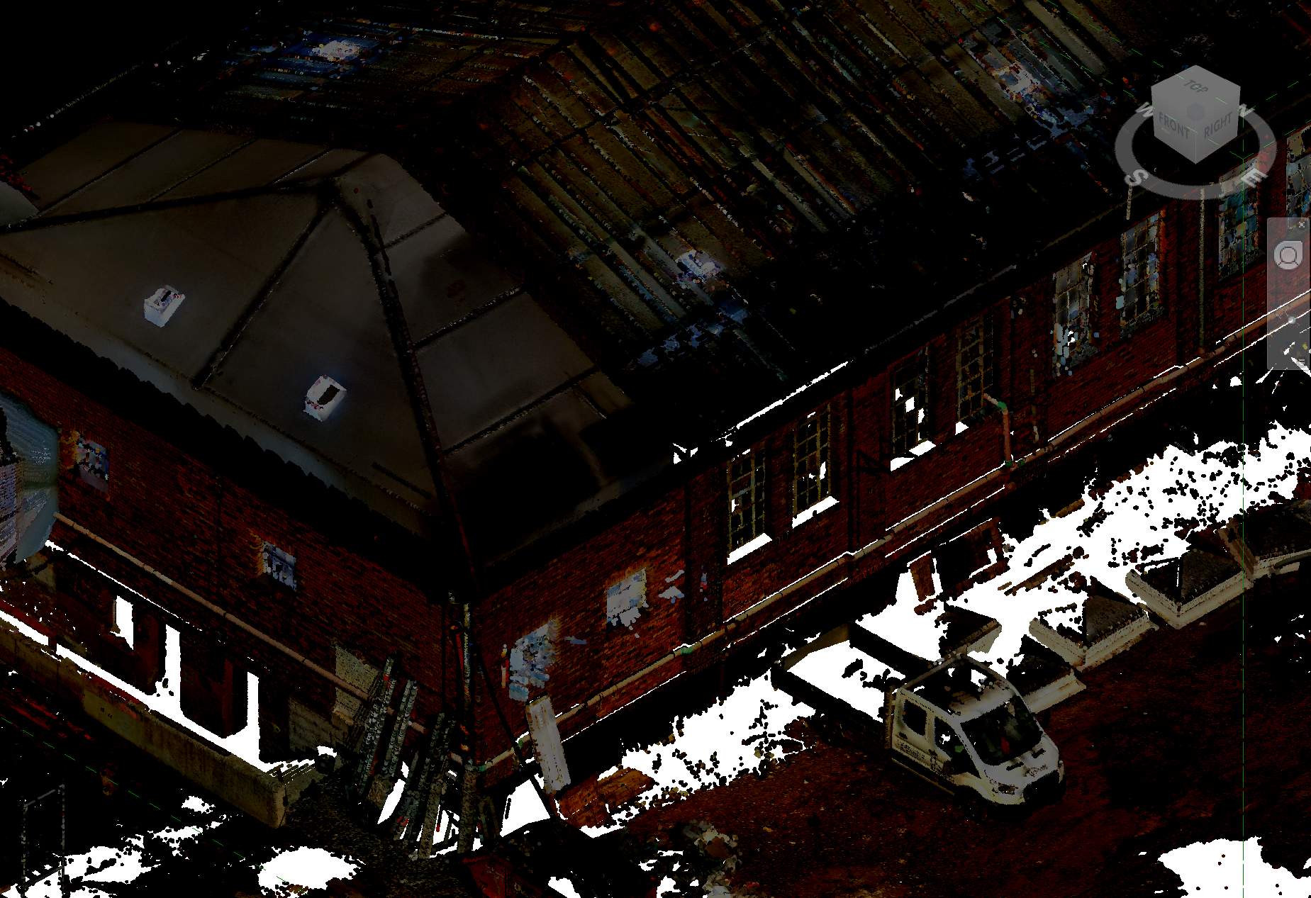
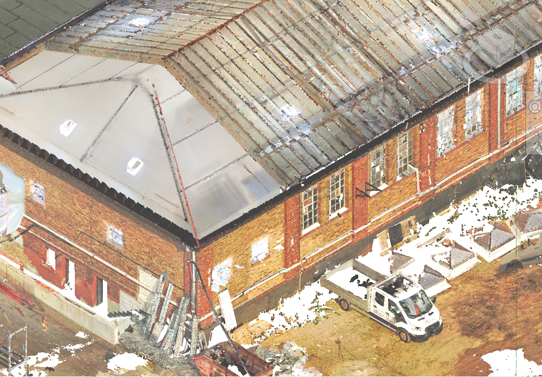
LiDAR scans are sometimes captured under poor lighting conditions, such as in the evening or in dimly lit indoor environments. In these cases, adjusting the brightness and contrast can help enhance visibility and reveal more details in the data.
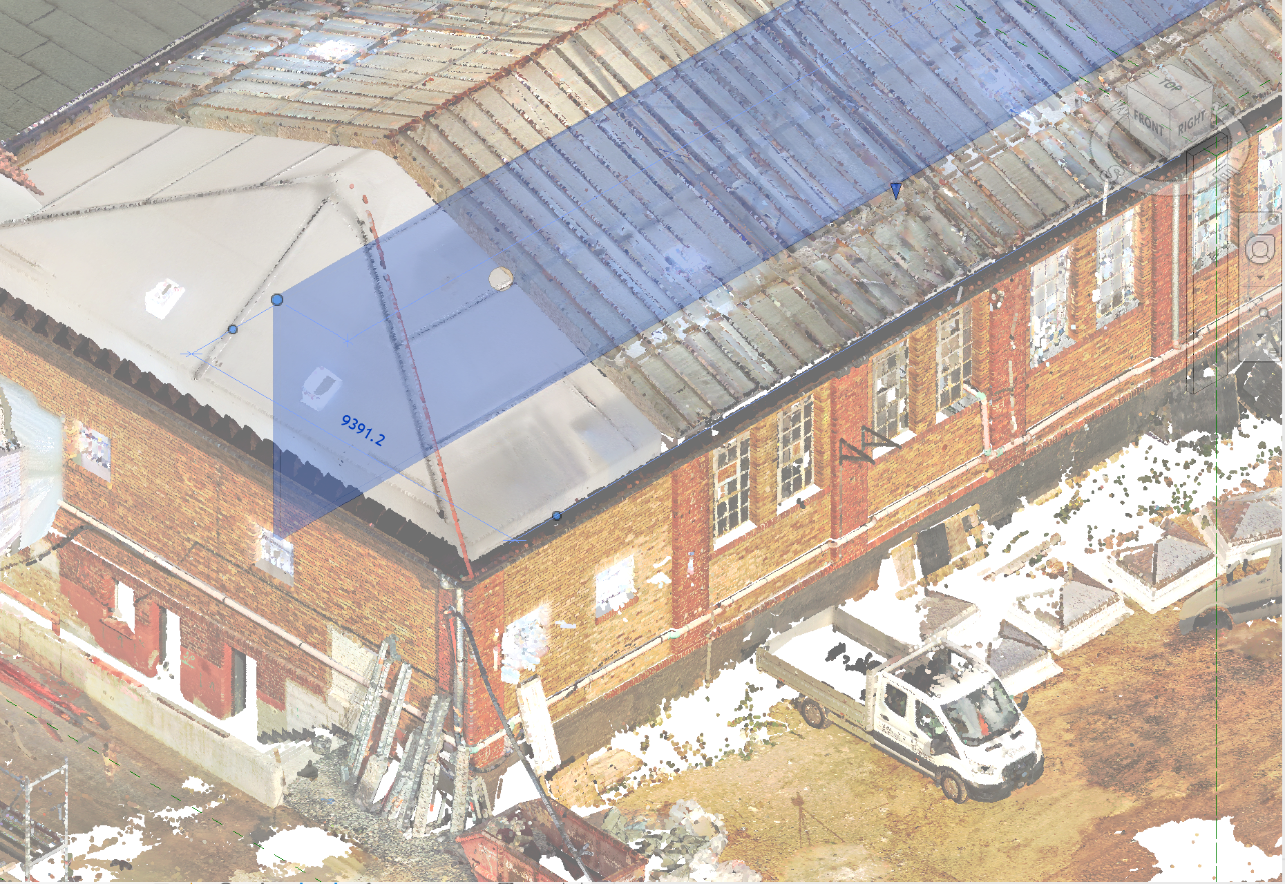
Transparency
The transparency of the point cloud can also be adjusted using a slider, allowing internal geometry to become visible that would otherwise be hidden behind the outer layers of the point cloud.
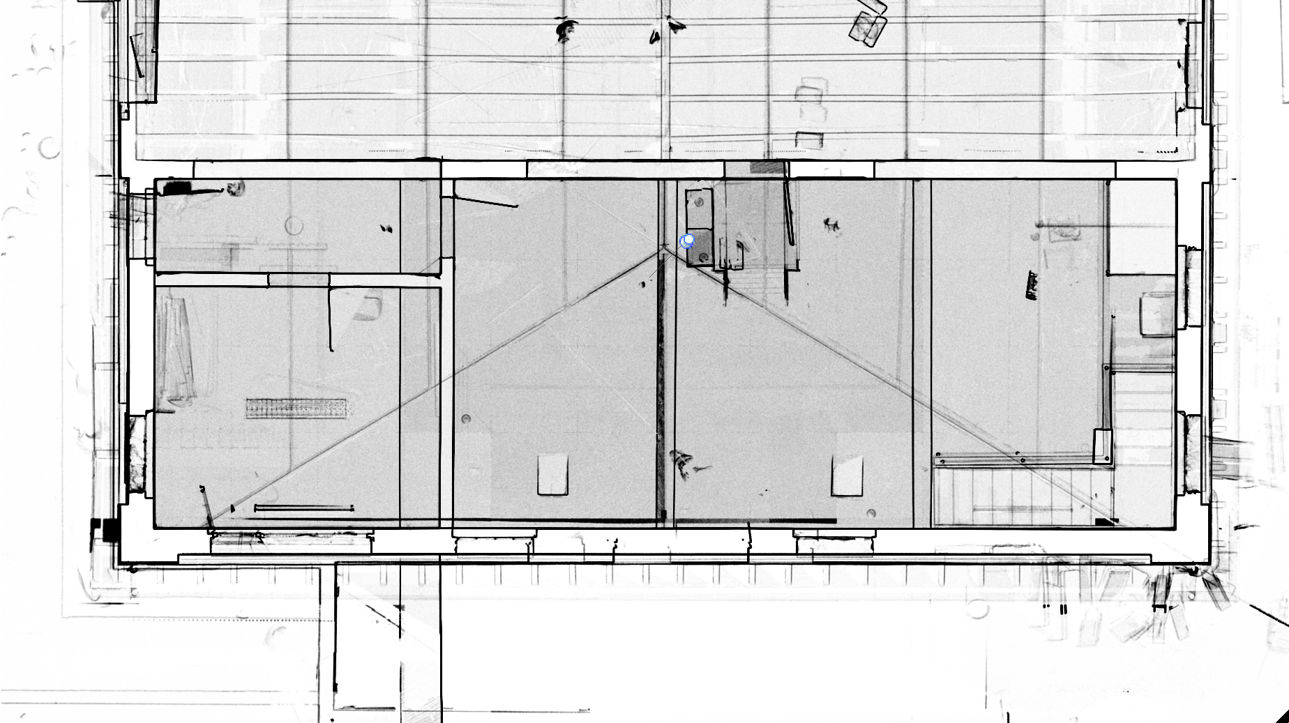
X-Ray Contrast
When working in an orthographic X-ray view, it can also be useful to adjust the X-ray contrast. Changing this setting alters how strongly different depth layers are emphasized, which can make certain structures more visible.
Lower contrast can help highlight larger structural elements such as walls and windows, while higher contrast can reveal finer details like beams, structural supports, or stair steps.
Since certain Revit geometry such as walls may also appear in monochrome white and black, it can sometimes be difficult to distinguish them from the contour lines produced by the X-ray visualization. For this reason, the color used for the X-ray mode can be adjusted with the following button:
In this example the X-ray color was adjusted to red make the two make the already modeled exterior wall better visible:
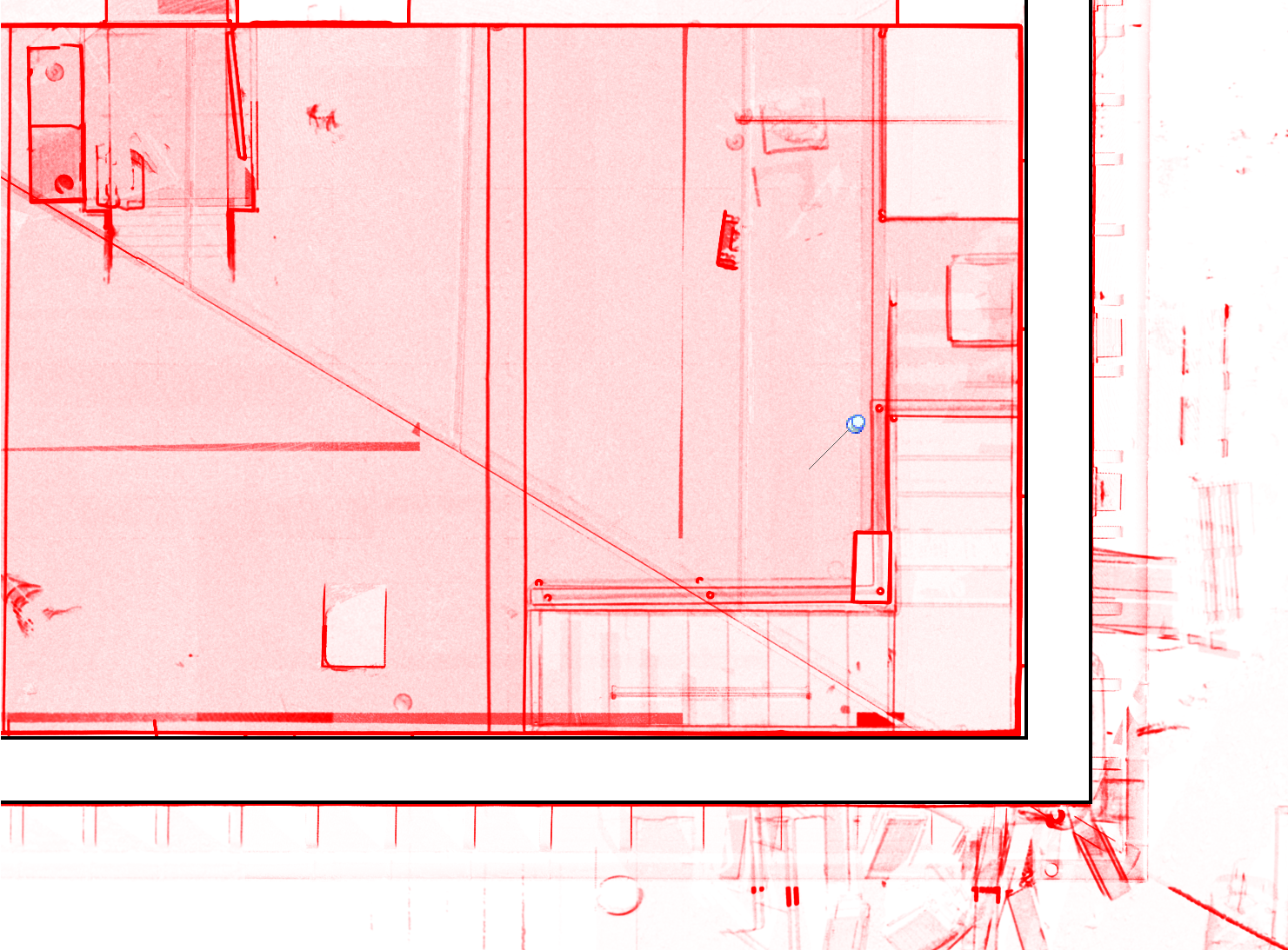
Additionally, it is also possible to display each point cloud in the X-ray view with its own individual color, which can further improve visual separation and make structures easier to interpret.
Finally, to go back to the default settings click on the Reset to default button.
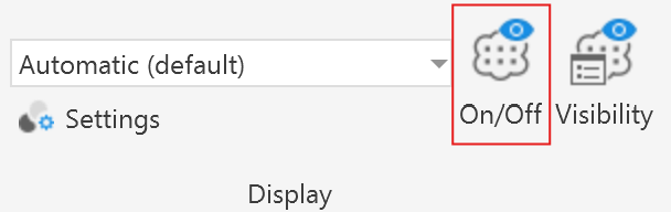
Visibility of All Point Clouds
With the On/Off-button depicted in this screenshot, it is possible to toggle the visibility of all point clouds in the current view at once.
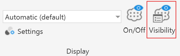
Visibility of Individual Point Clouds
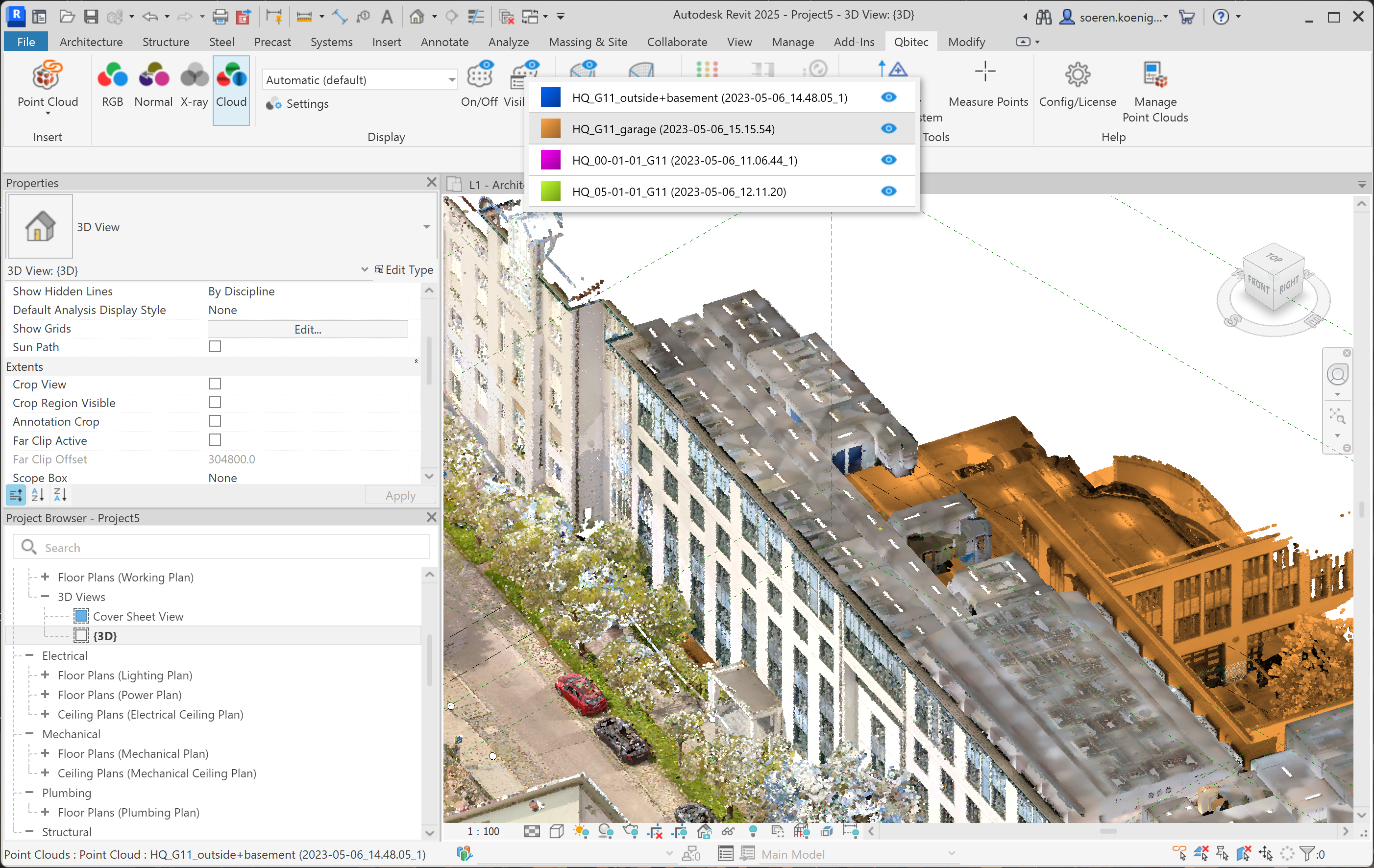
The hide and show individual point clouds first click on the Visibility-button.
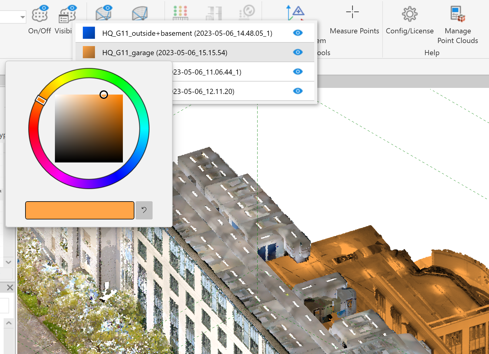
This opens a list of all point clouds in the scene. When a specific point cloud is selected it is highlighted by its associated color while non selected point clouds are displayed with its normal RGB colors.
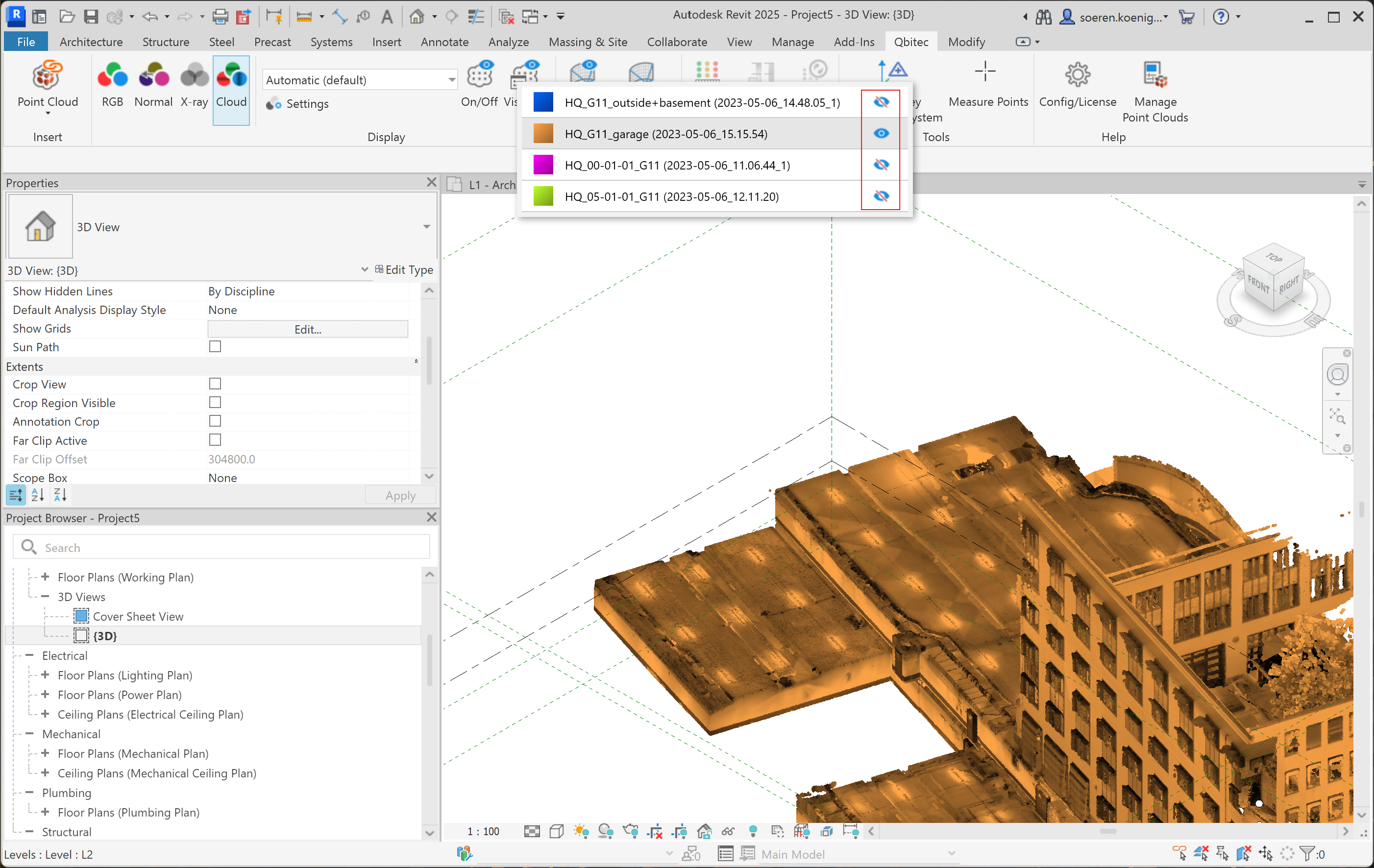
To hide or show single point clouds you can use the blue eye symbol button behind each cloud in the list. In the example The blue, pink and green point clouds are hidden and only the orange one is shown.
If you are not satisfied with the automatically assigned colors, you can change them by clicking on the colored rectangle in front of the point cloud name.